Sanguinololu Assembly
Contents
- Notes
- Step 1 - Check Kit Contents
- Step 2 - 1kΩ resistor
- Step 3 - 4.7kΩ resistors
- Step 4 - 100kΩ resistors
- Step 5 - 100nF capacitors
- Step 6 - Reset Button Tactile Switch
- Step 7 - 40-pin IC socket
- Step 8 - 16MHz resonator
- Step 9 - green LED
- Step 10 - 10µF capacitors
- Step 11 - headers
- Step 12 - Endstop Voltage Selector
- Step 13 - USB socket
- Step 14 - 100µF and 1000µF capacitors
- Step 15 - 7805 5v regulator and 0.33µF capacitor
- Step 16 - Power and Heater Screw Terminals
- Step 17 - IRLB8743 Power Mosfets
- Step 18 - Enhance Bed Heater Traces
- Step 19 - Electrical Testing
- Step 20 - FTDI FT232R USB-Serial IC
- Step 21 - ATMEL ATMEGA644p microcontroller
- Step 22 - Insert Jumpers
- Step 23 - Smoke Test
- Step 24 - 12v test
- Step 25 - I/O Test
- Step 26 - Print!
Notes
- I have endeavoured to select components that will allow this board to run from voltages as high as 30v
- Watch out for POLARITY WARNING - this is your key to identifying polarised components. I include an estimate of what might happen if the part is inserted incorrectly but of course there's a huge range of possible failure modes including subtle intermittent failures.
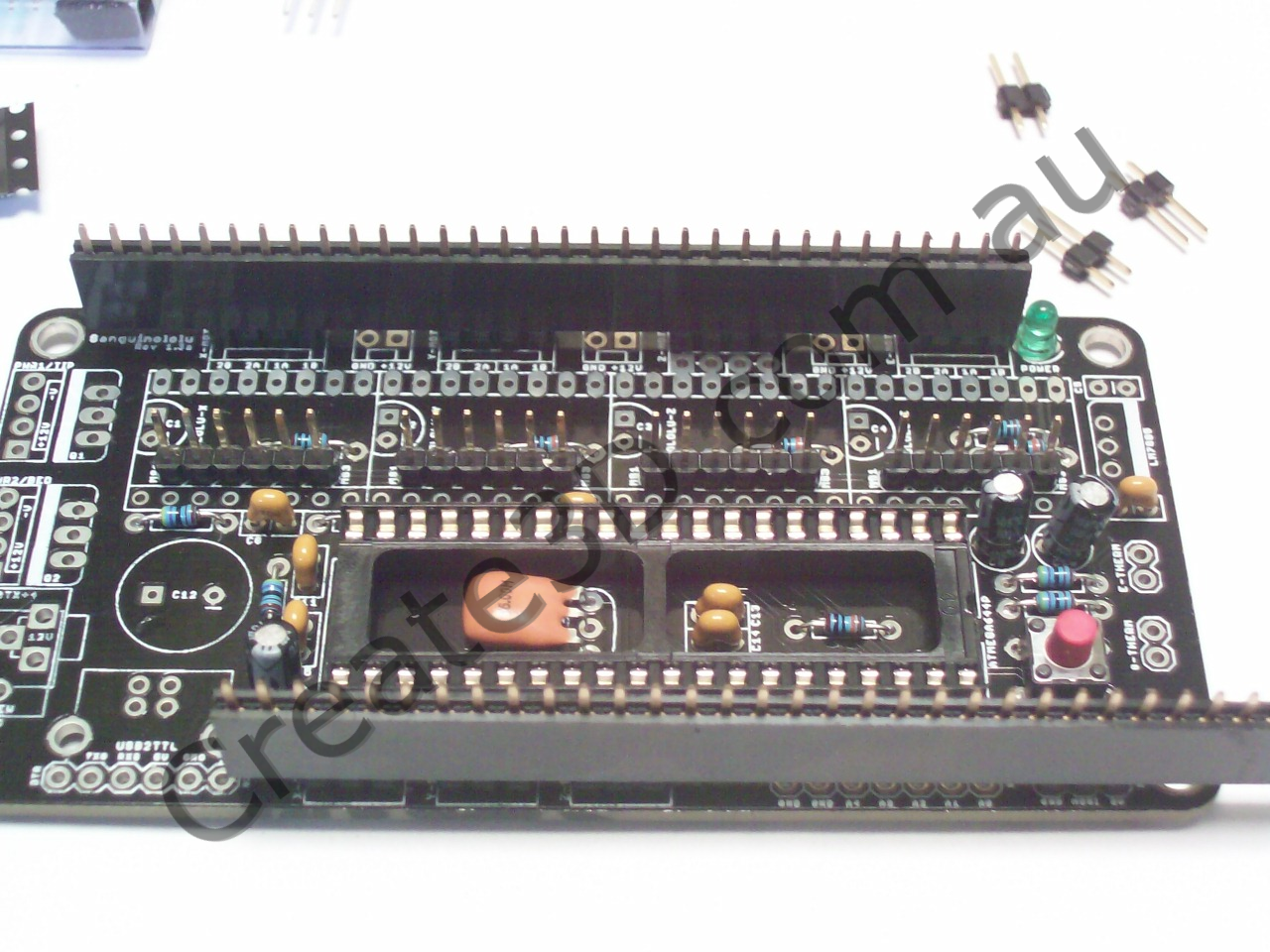
Step 1 - Check Kit Contents
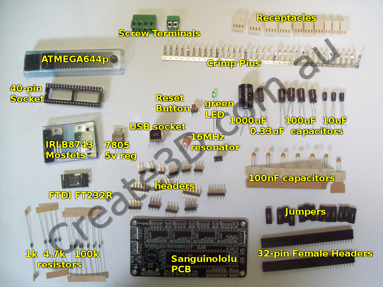
Kit should contain:
Active Components:
- 1x Sanguinololu PCB
- 1x Atemga644p 40 pin IC
- 1x FTDI FT232R USB-Serial Surface Mount IC (this can be pre-soldered to your PCB for an extra $5)
- 2x IRLB8743 or similar power mosfets, TO-220 package
- 1x 7805 or similar 5v regulator, TO-220 package
Passive Components:
- 1x green 3mm LED
- 1x tactile pushbutton
- 1x 16MHz resonator
- 1x 1000µF electrolytic capacitor
- 1x 0.33µF electrolytic capacitor
- 4x 100µF electrolytic capacitors
- 3x 10µF electrolytic capacitors
- 7x 100nF ceramic capacitors
- 1x 1kΩ resistor
- 4x 4.7kΩ resistors
- 7x 100kΩ resistors
Sockets and Connectors:
- 1x 40-pin IC socket
- 2x 32x1 32-pin female header sockets
- 1x USB type B socket
- 1x 4-pin Right-Angle Minifit Molex socket (ATX12V socket, not pictured)
- 3x 2-pin screw terminal (or 1x 4-pin and 1x 2-pin)
- 1x 2x3 6-pin header
- 4x 1x6 6-pin header
- 1x 2x7 14-pin header (or 2x 1x7 7-pin headers)
- 3x 3x1 3-pin headers
- 4x (or 5x) 4x1 4-pin headers
- 3x 2x1 2-pin headers
- 12x regular jumpers
- 1x jumper with tag (or no jumpers and 13 tagged jumpers, 12 will need tags cut off)
- 4x (or 5x) 4-pin receptacles
- 3x 3-pin receptacles
- 3x 2-pin receptacles
- 33x crimp pin to match receptacles
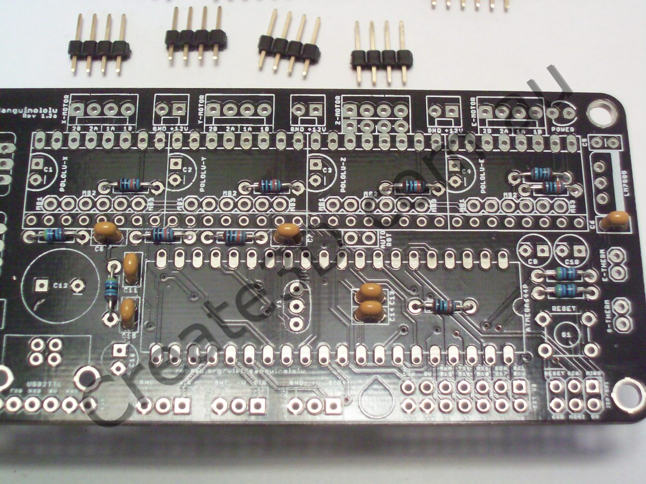
Step 2 - 1kΩ resistor
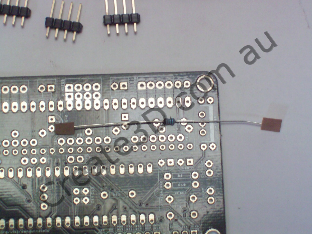
| 1 | 0 | 0 | 1 | 1% |
| 1 | 0 | 2 | 5% |
Step 3 - 4.7kΩ resistors
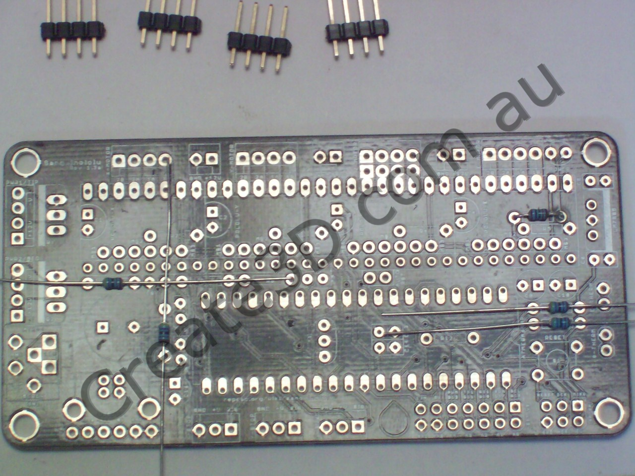
| 4 | 7 | 0 | 1 | 1% |
| 4 | 7 | 2 | 5% |
Step 4 - 100kΩ resistors
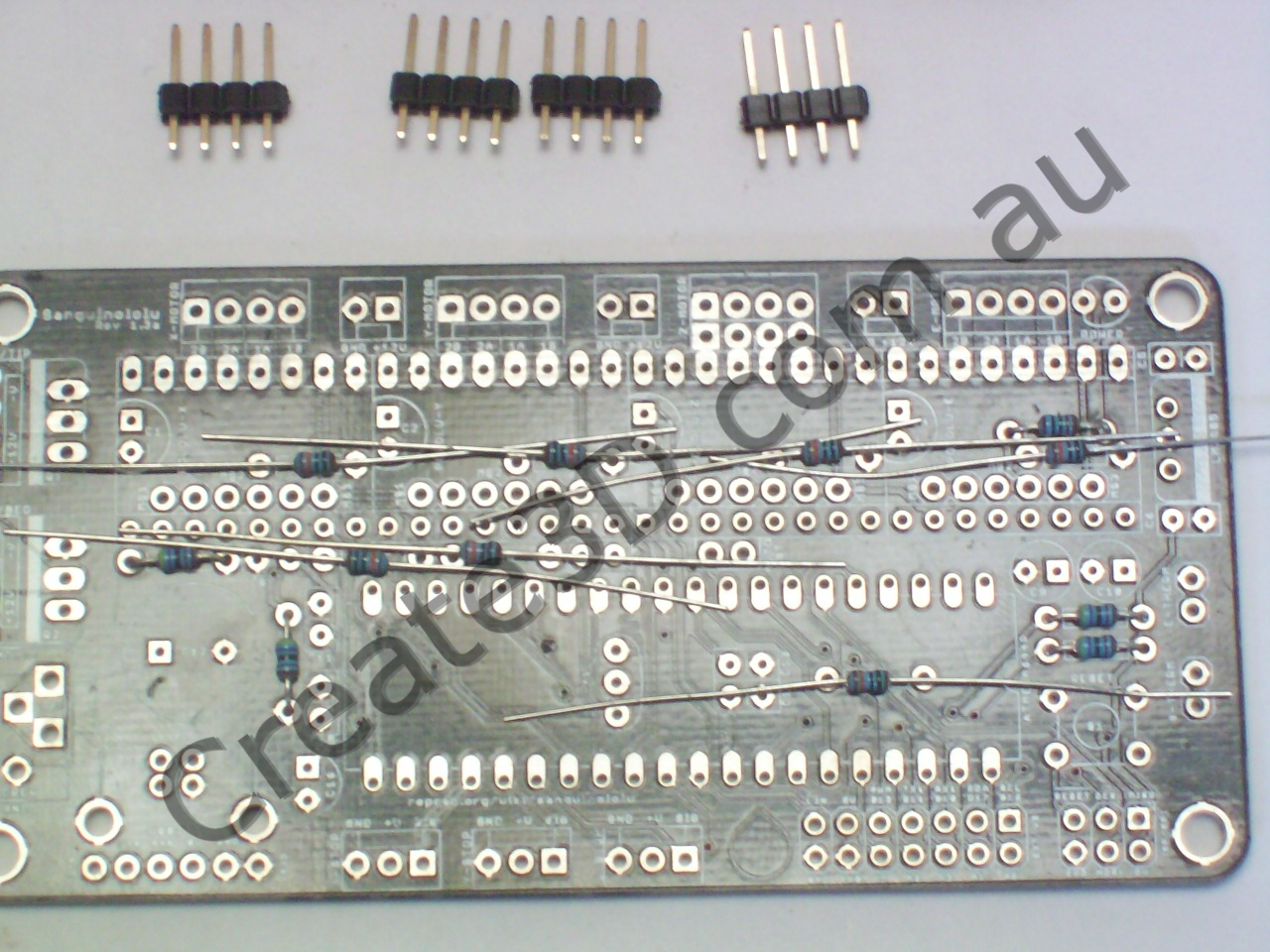

| 1 | 0 | 0 | 3 | 1% |
| 1 | 0 | 4 | 5% |
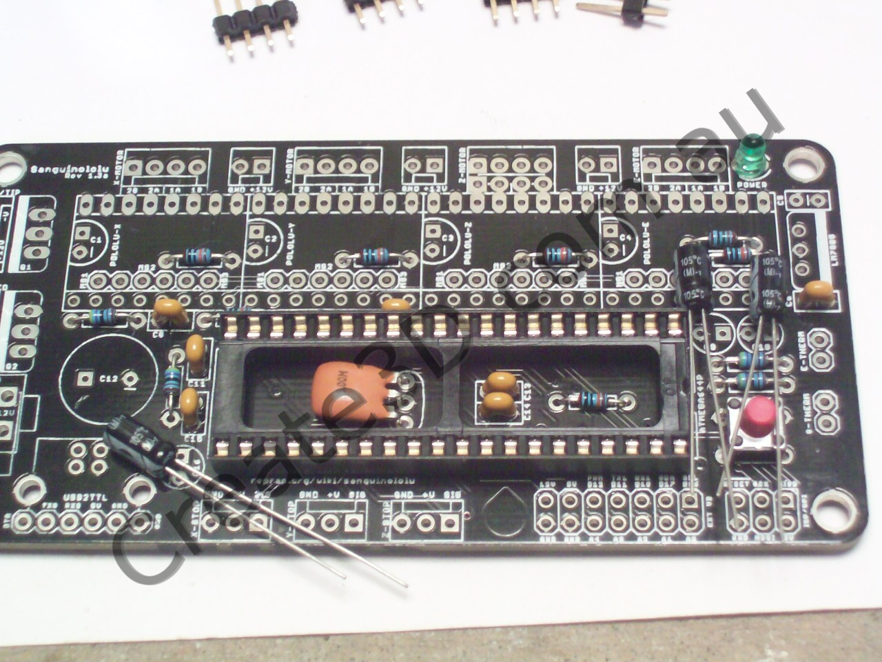
Step 5 - 100nF capacitors
104
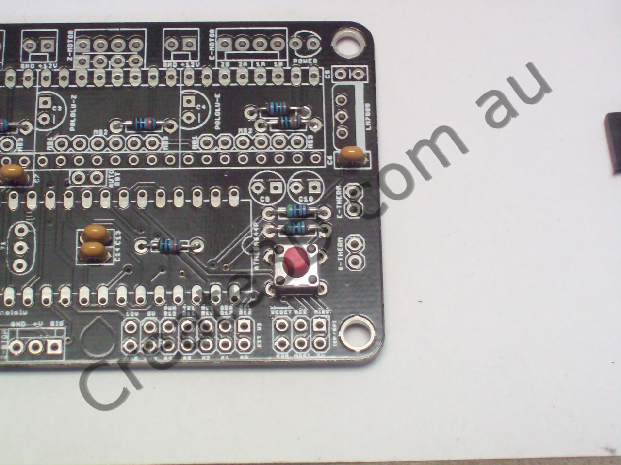
Step 6 - Reset Button Tactile Switch
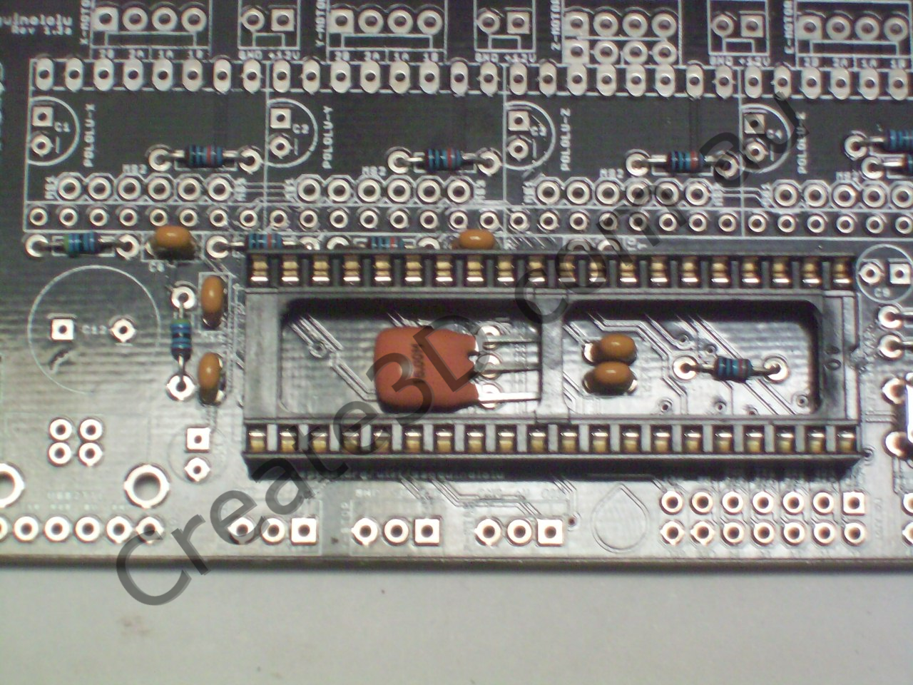
Step 7 - 40-pin IC socket

POLARITY WARNING: This part should be inserted in the correct orientation to aid you in inserting the IC the correct way around. It will work fine if inserted incorrectly, but may be confusing later on when you insert the ATMEGA644p microcontroller into it.
Step 8 - 16MHz resonator
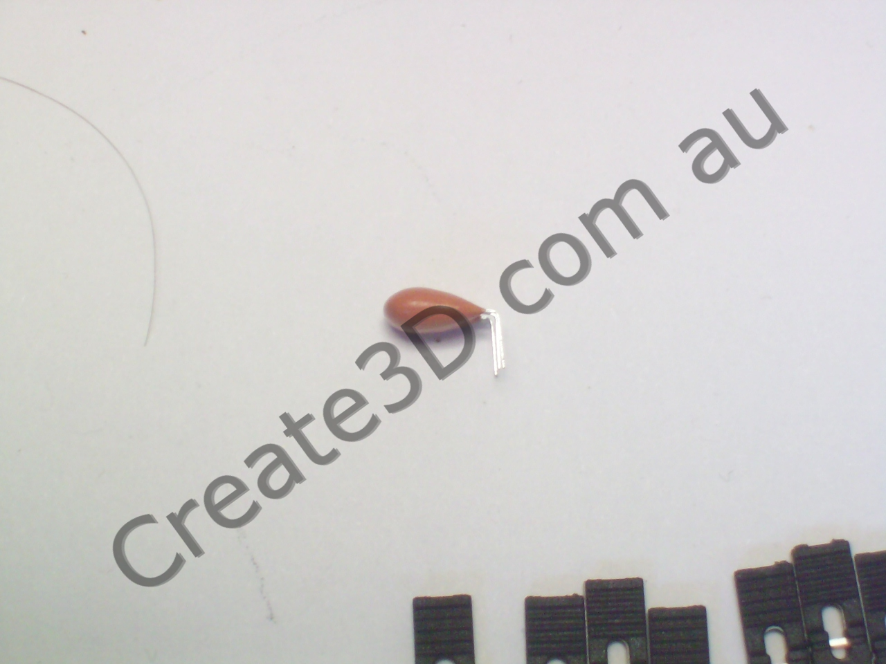
16.00M
Bend the leads at a 90 degree angle. This part must lay flat under the IC. It can go either way, but I like to insert it labelled side up.
Step 9 - green LED

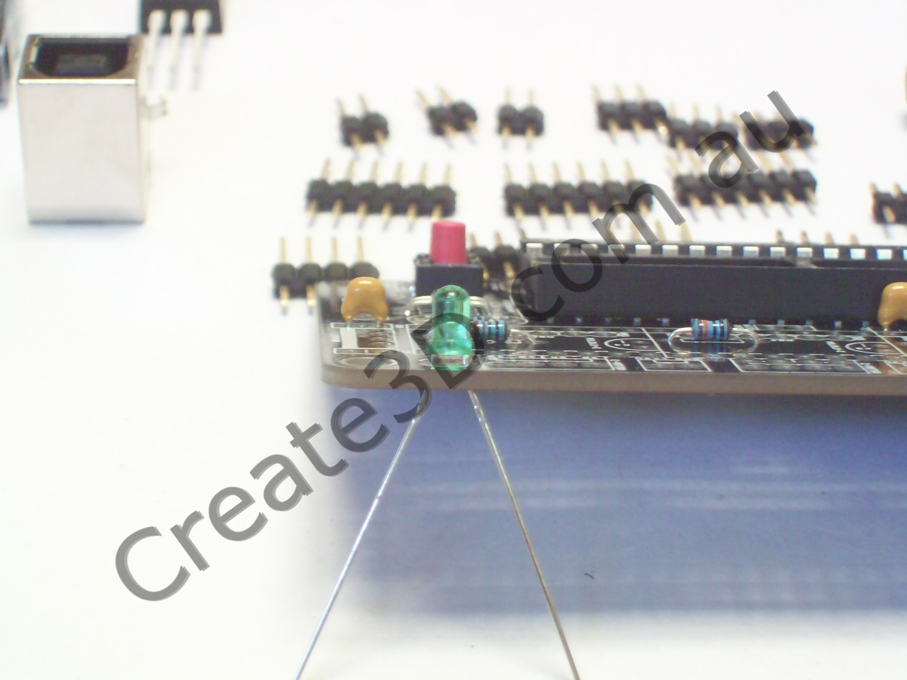
POLARITY WARNING: This part will only work if inserted correctly. The PCB has the chamfered side marked. If inserted incorrectly, it won't glow. No other damage should occur.
Step 10 - 10µF capacitors
POLARITY WARNING: This part will only work if inserted correctly. The PCB has a "-" next to the negative pin, and the capacitor body has the negative pin marked clearly. Incorrect polarity will cause these to leak stinky gunk and possibly prevent your board from working correctly.
Step 11 - headers
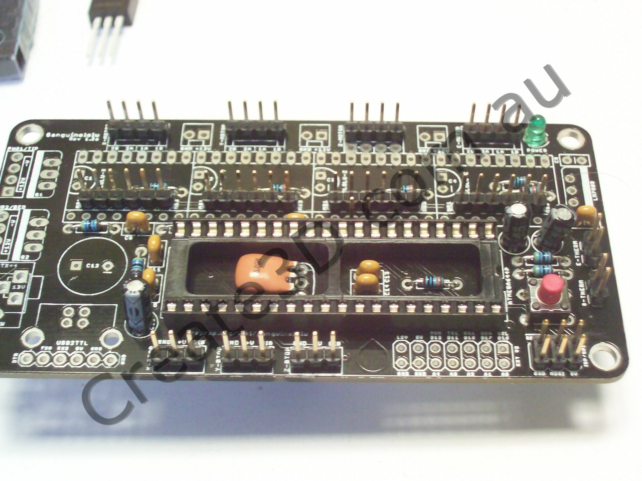
Hint:use the 32-pin female headers to help keep male headers aligned and vertical while soldering
Step 12 - Endstop Voltage Selector

WARNING: Set this to 5v unless you know exactly what you are doing!
Bridge one side of this solder jumper to choose between sending 5v or 12v to your endstops.
Step 13 - USB socket
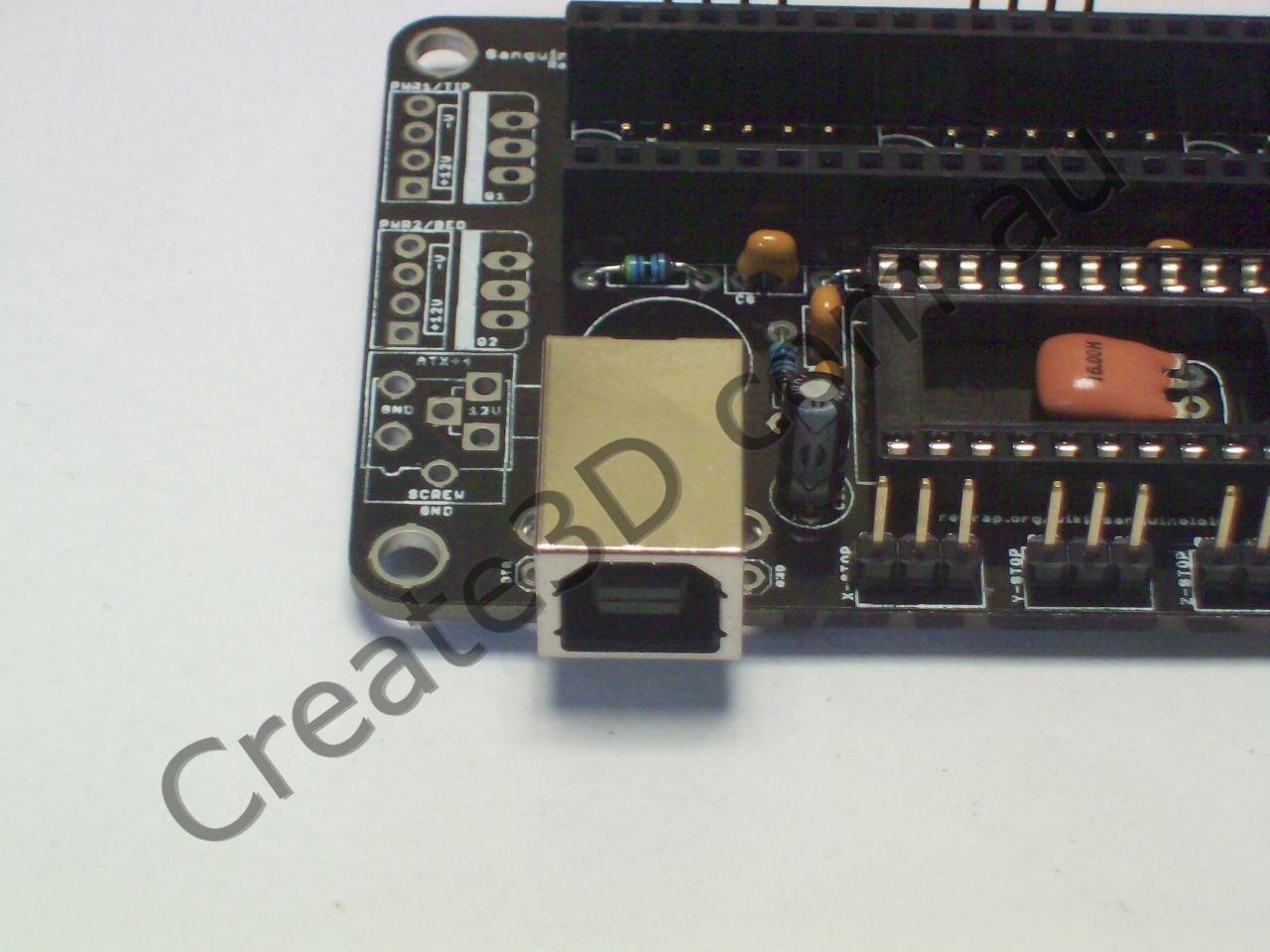
Insert into board, solder, and trim mounting pins short.
Note: It's possible that the metal housing of this piece could short the Serial pins underneath. I insert a thin piece of cardboard underneath its front edge so that it will be spaced and not touch these pads.
Step 14 - 100µF and 1000µF capacitors
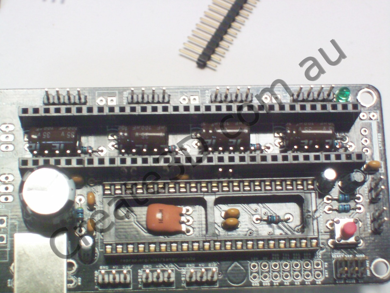
POLARITY WARNING: This part will only work if inserted correctly. The PCB has a "-" next to the negative pin, and the capacitor body has the negative pin marked clearly. Incorrect polarity will cause them to explode and fire stinky gunk everywhere, or emit fire.
Bend the pins of the 100µF capacitors over MINDING POLARITY so that they can lie flat under your A4988 carriers ("pololus"). They won't lie perfectly flat due to the resistors, but they will go low enough to not collide.
The 1000µF capacitor goes straight in and sits vertical. Add hot-glue if you're worried about vibration.
Step 15 - 7805 5v regulator and 0.33µF capacitor
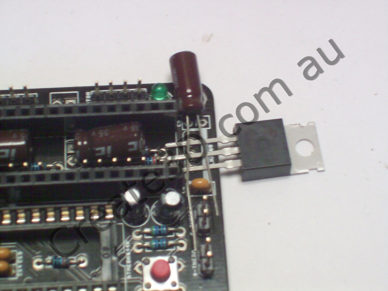
POLARITY WARNING: This part will only work if inserted correctly. The PCB has a dense line to indicate which side the tab goes on.
IMPORTANT: The middle pin of this part MUST be properly and securely soldered before you apply 12v to the board! There have been a few cases (not with my customers, in other parts of the world) where the middle pin wasn't correctly soldered, and all the ICs got burnt by 12v!
Bend the pins of the 0.33µF capacitor in a gentle S shape, like the mosfets below so that it fits beside the regulator.
Note: This IC has the same package as the IRLB8743 power mosfets (below). Don't get them confused!
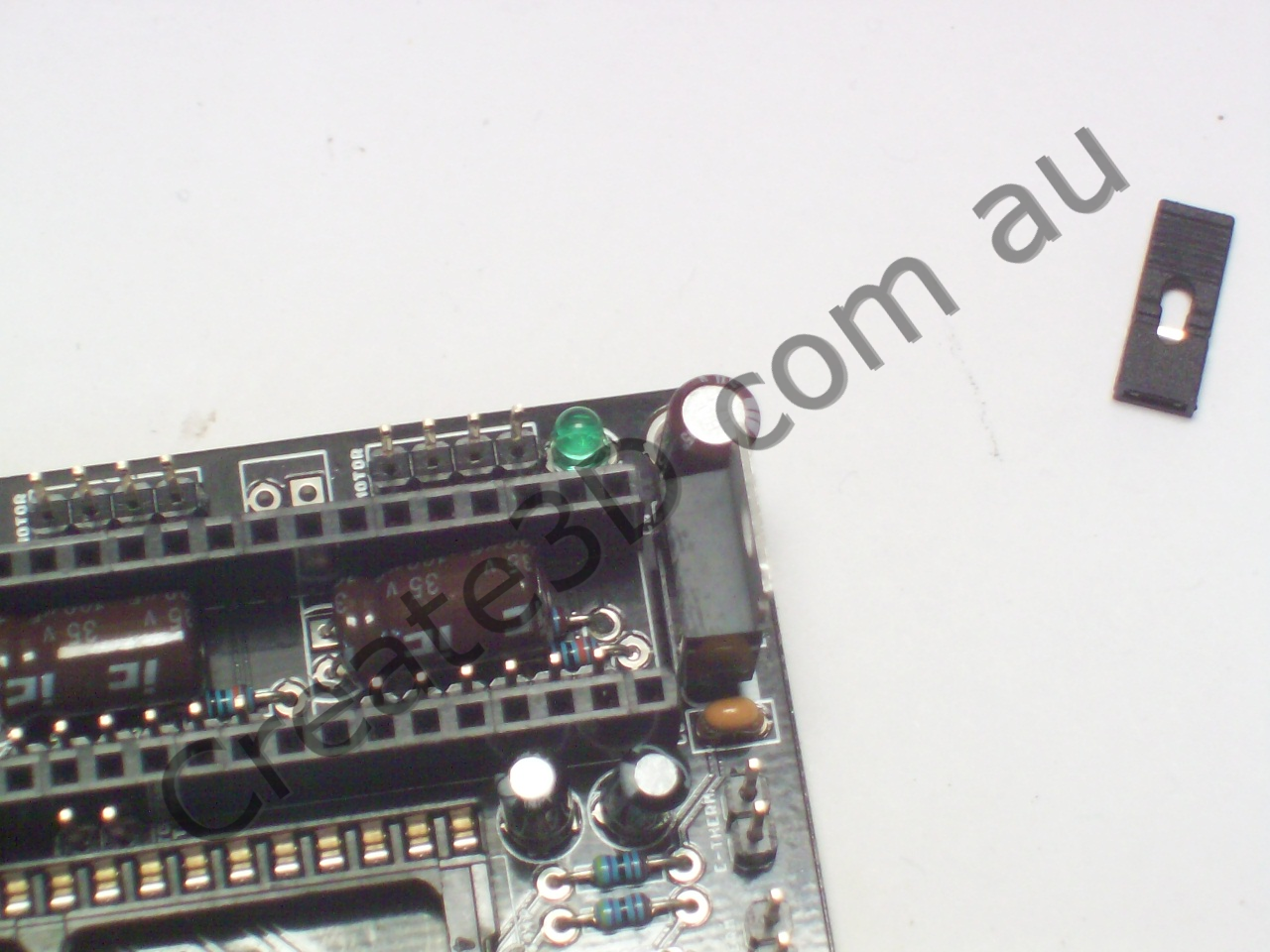
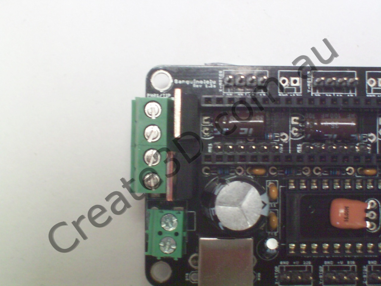
Step 16 - Power and Heater Screw Terminals

Note: Substitute ATX12V connector (not pictured) for lower screw terminal if you prefer to have that connector
Step 17 - IRLB8743 Power Mosfets
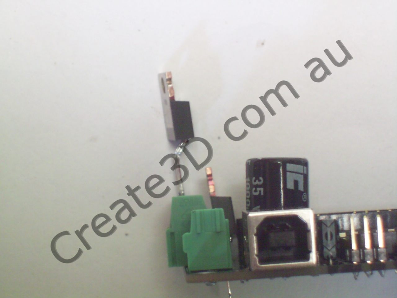
POLARITY WARNING: These parts will only work if inserted correctly. The PCB has a dense line to indicate which side the tab goes on.
Bend the leads in a gentle S as pictured so they can stand vertical behind the screw terminals. If they don't stand vertical, they may foul on the A4988 carriers ("pololus") later on.
Note: These mosfets have the same package as the 7805 5v regulator (above). Don't get them confused!
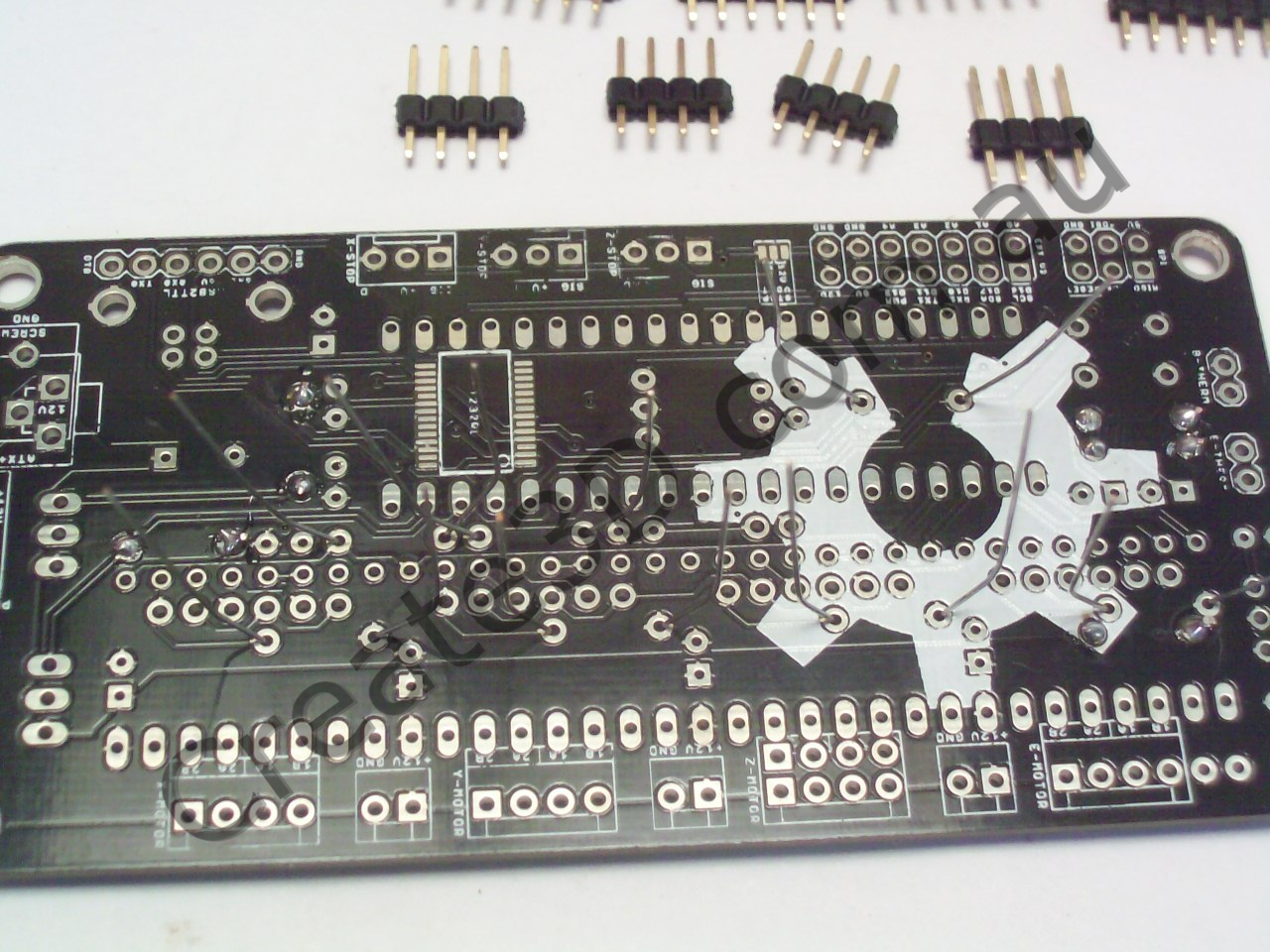
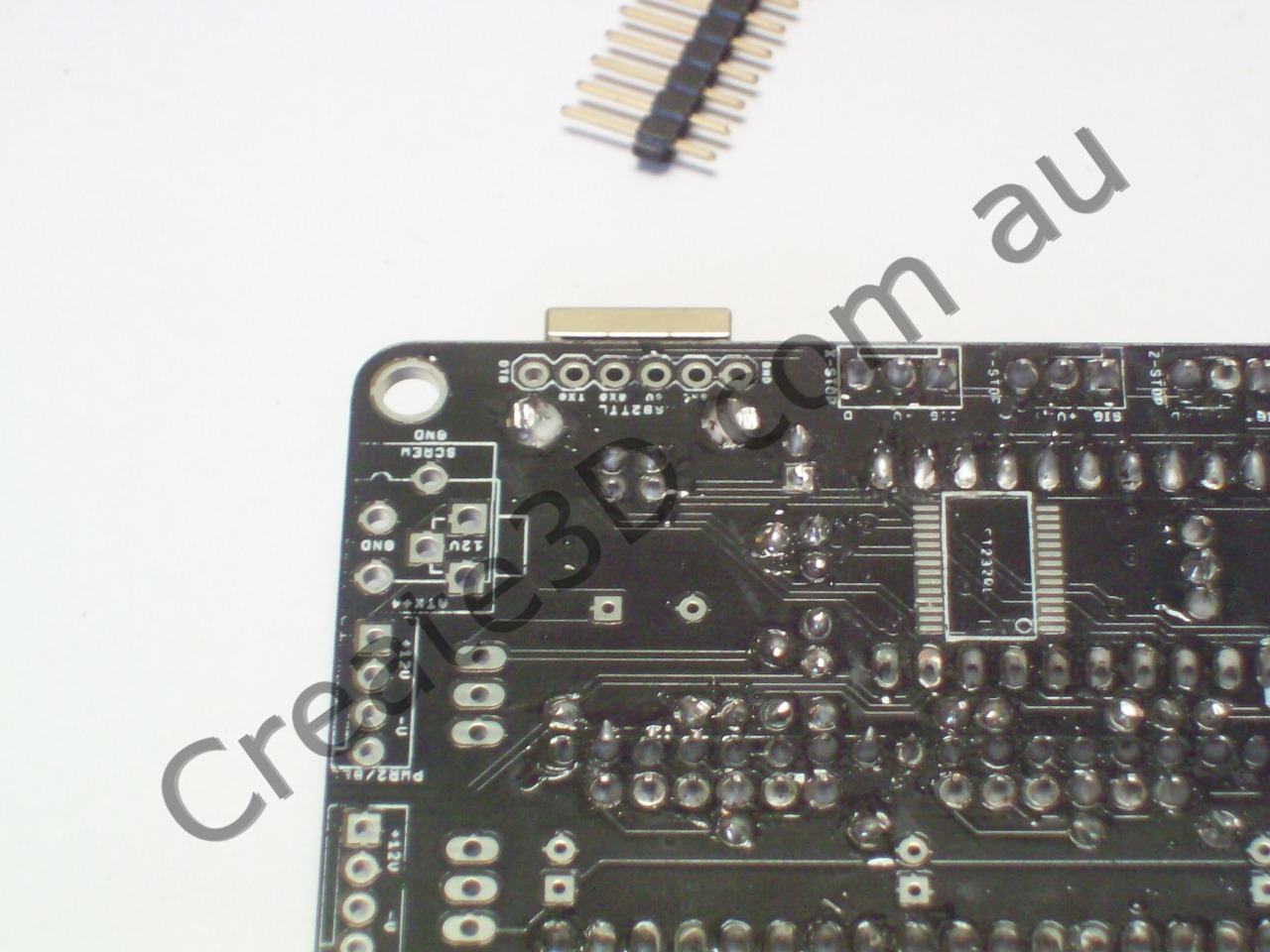
Step 18 - Enhance Bed Heater Traces
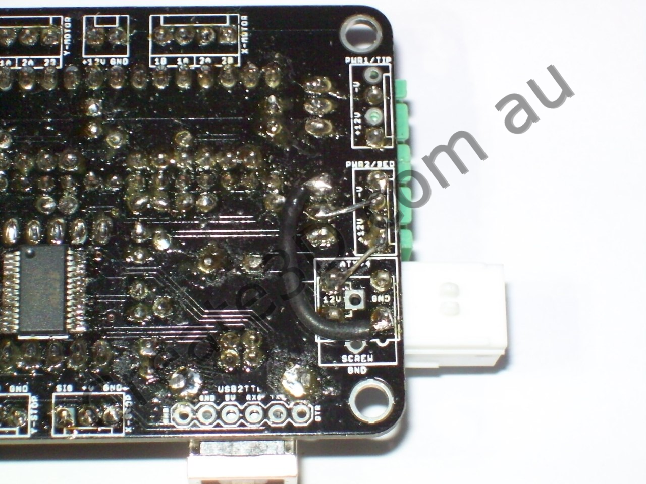
The board design has some questionably small traces between the power connector and the Bed Heater output. The pictured additions give an alternative path which should carry a higher current without problems.
Step 19 - Electrical Testing
IMPORTANT: This is the time to do electrical testing if you don't like buying new silicon for a silly mistake.
The MOST IMPORTANT thing to check is that there's no path from 12v to the 5v rail, or any logic pin. If there is a short from 12v to almost anything else, the silicon chips on your board WILL die and possibly emit fire!
Use the continuity tester feature on your multimeter, beeper if you have one.
NOTE: it /will/ beep for a moment when you first test between various power pins (ie 12v/ground, 12v/5v, 5v/ground) due to the capacitors. This is normal. You have a fault if it continues to show continuity for more than a second or two.
After checking for shorts between the mosfet gate pin and ground, the mosfet may remain on. Simply short the gate pin to ground momentarily to turn it back off. Ensure that it does turn off!
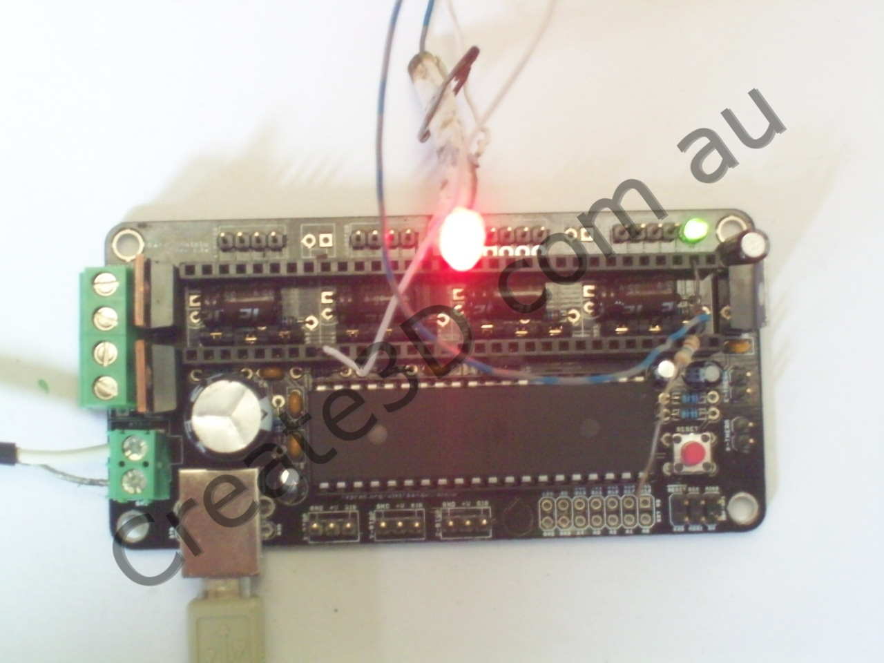
If you're reasonably confident that there are no shorts, connect to your USB port. The green led should light up. Check that you're seeing 4.6v or more across the 5v rail.
Disconnect from USB, and if you're confident there are no shorts on 12v, apply 12v power. The green led should be the same brightness as the USB test. Check again that your 5v rail is reading at around 4.9 volts.
When you are CERTAIN that your 12v power isn't getting anywhere it shouldn't be and that all else seems to be well, continue with inserting the ICs
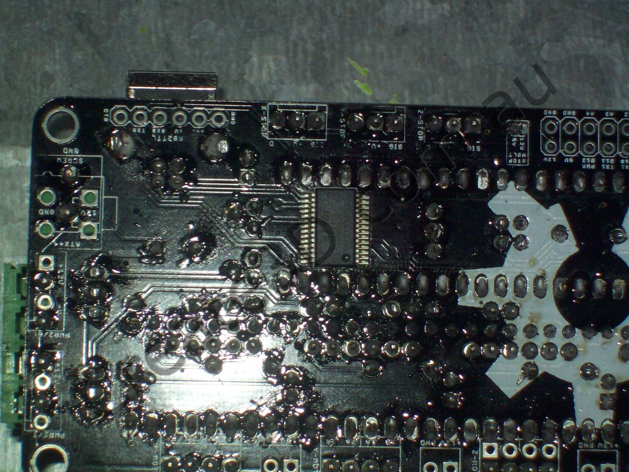
Step 20 - FTDI FT232R USB-Serial IC

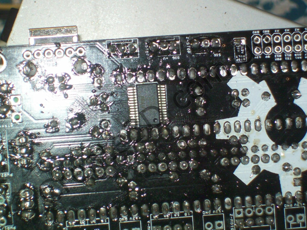

POLARITY WARNING: This chip must be inserted in the correct orientation or it may be damaged or emit fire! There is a circle marked on the PCB at one end, this should line up with a circle on the chip body itself.
NOTE: You can have this chip pre-soldered for you for an extra $5 when ordering
Some people find soldering this IC a little daunting. Take your time, be careful and you'll be fine.
- Place IC on PCB, ensure it is in the correct orientation!
- Solder one corner pin. Don't worry if it moves slightly.
- If IC isn't well aligned to pads, re-melt the pin you just soldered and move it into position. Do not worry if it's rotated slightly.
- Once the first pin has cooled, rotate it so that all pins line up with their pads.
- Solder the diagonally opposite corner pin.
Now the IC is held securely in place - If you have rotated the IC, momentarily re-melt the first pin to relieve any stress.
- Solder the rest of the pins one by one. Pause frequently to allow the IC to cool down. If you bridge two pins, simply use solder wick or a solder sucker to remove solder and clear the bridge.
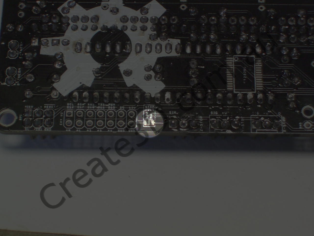
- Note: Pins 25 and 26 are connected on the board itself (see photos, two pins up from lower left). Since the pads are connected, you may find it difficult to clear a bridge between these pins. Since they're connected anyway, don't worry about it, leave the bridge.
Step 21 - ATMEL ATMEGA644p microcontroller
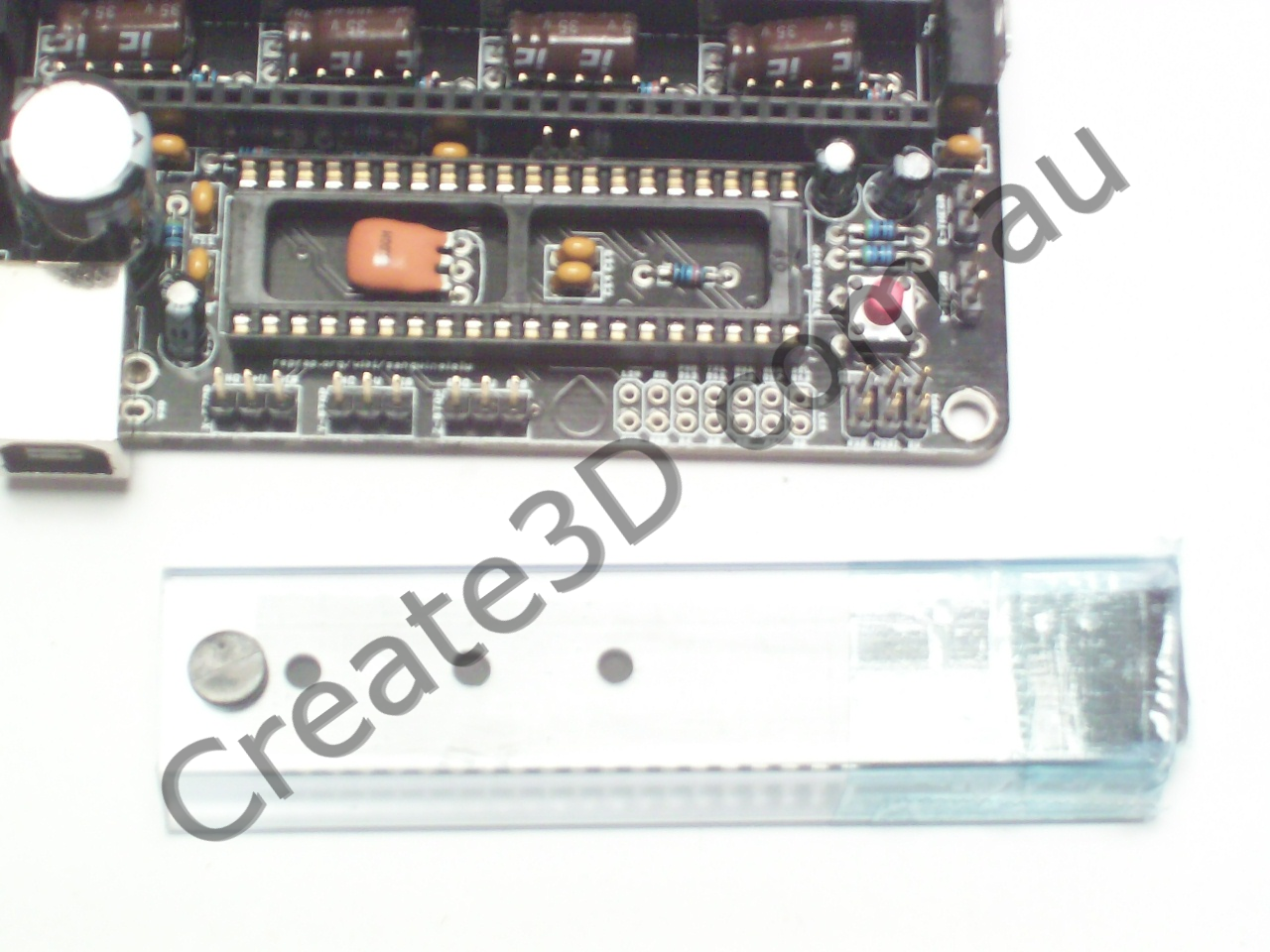
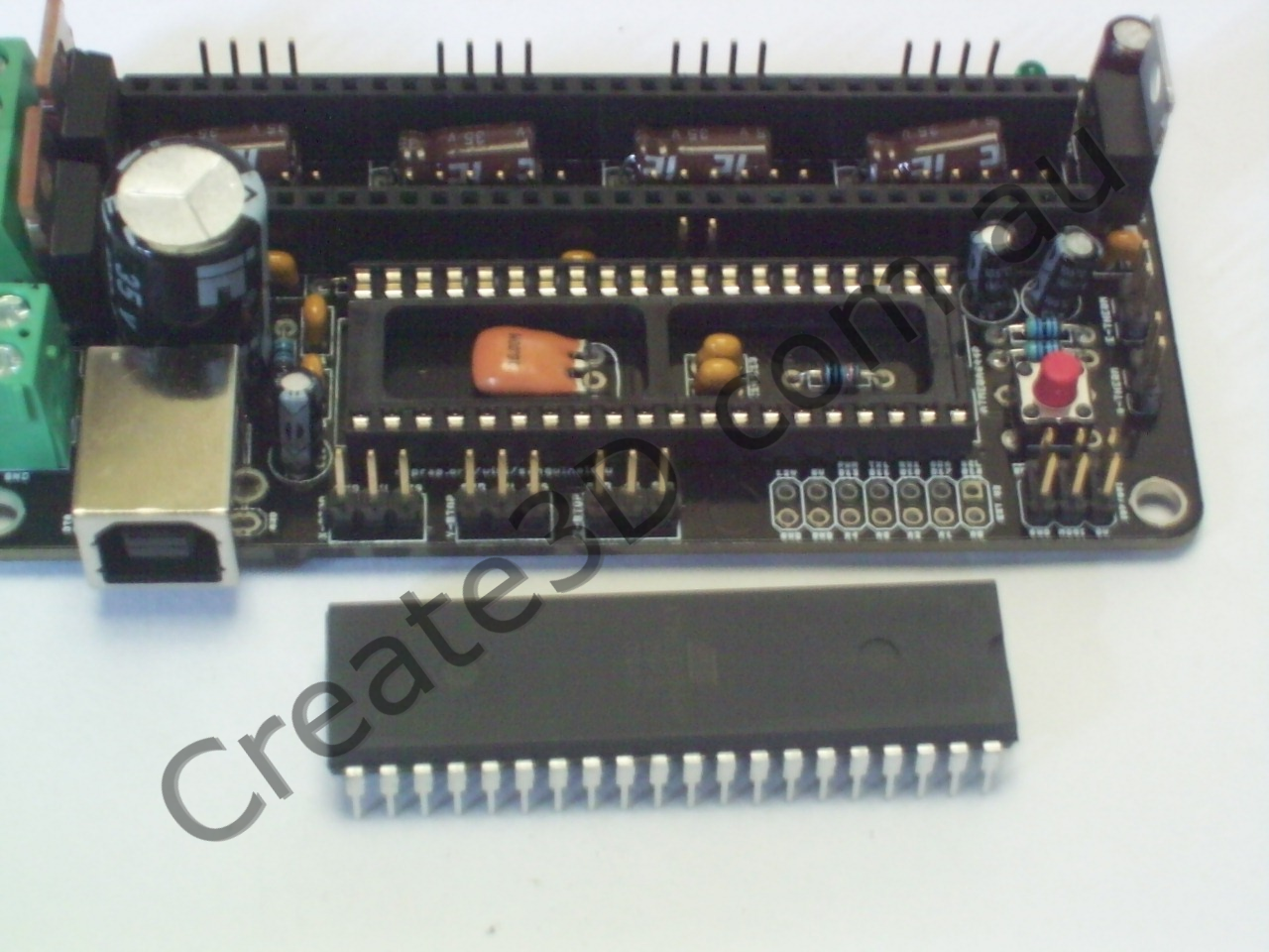

POLARITY WARNING: This chip must be inserted in the correct orientation or it may be damaged or emit fire! There is a semicircle marked on the PCB at one end, this should line up with a semicircle on the chip body itself, or be at the same end as a circle at one corner of the chip. If you inserted your IC socket the right way, this will help you identify the proper orientation.
You will have to bend the pins of the IC inwards for it to insert cleanly into its socket. I don't understand why all chips come this way, but they do.
I use either my bench vise (gently!) or do it by hand against a hard surface. I advise using the bench vise, as if you slip with the latter method you can damage the pins.
Step 22 - Insert Jumpers

Insert the 13 jumpers as shown.
The 12 jumpers under the A4988 carrier ("pololu") sockets select microstepping. With all 3 per set installed, you will get 16x microstep. Most 3D printers use 16x microstep on all 4 axes.
The jumper with a tag goes just above the ATMEGA644p, this is your auto-reset jumper. Insert for uploading firmware and to enable software reset, Remove to prevent any reset except by power interruption or pressing the button.
Step 23 - Smoke Test
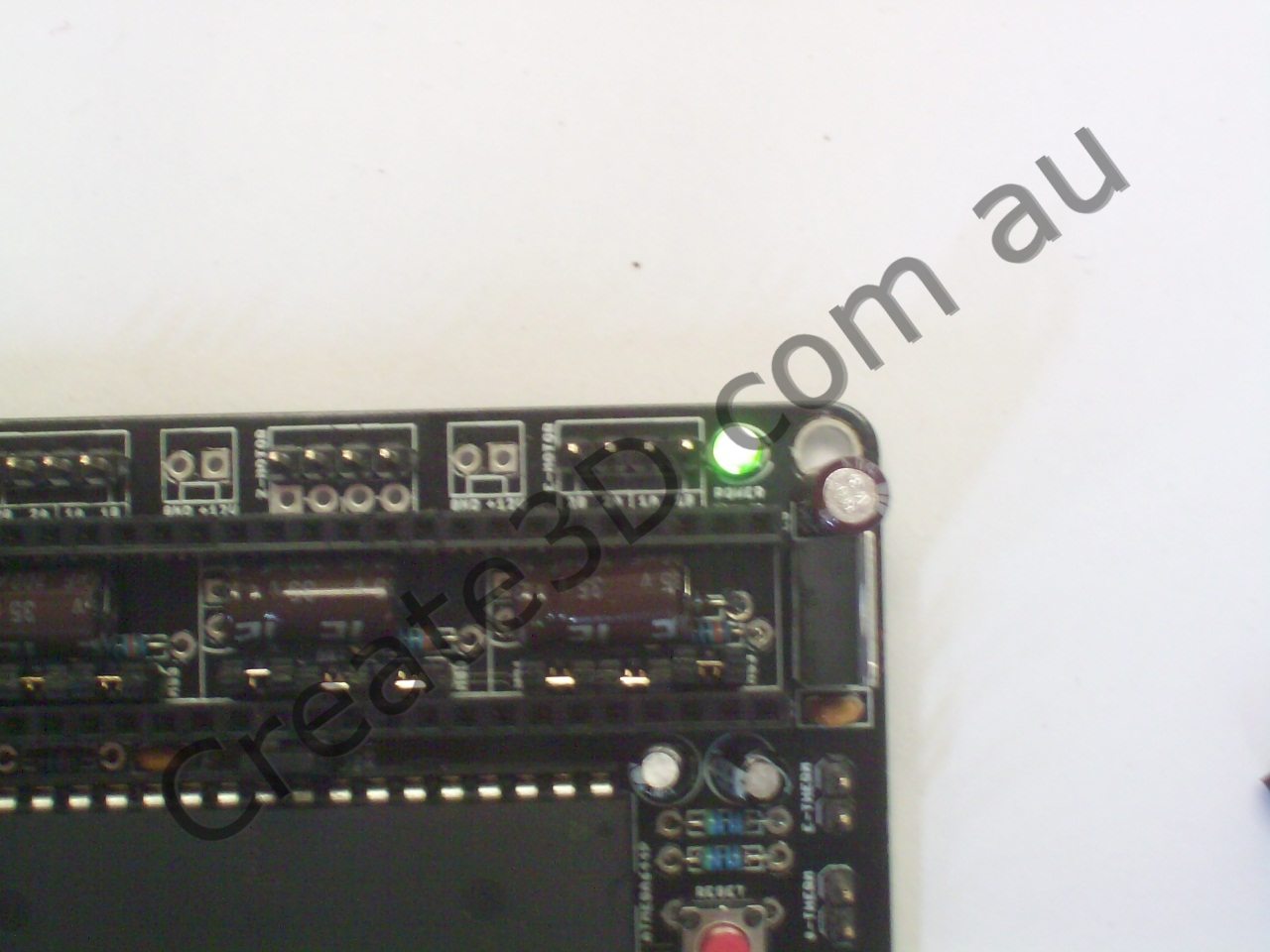
This is the first moment of truth! After making sure there are no shorts between 5v and ground, plug into your USB port and ensure that the green LED shines.
Step 24 - 12v test

This is the second moment of truth! After ensuring that there are no shorts between 12v and anything else, connect 12v ONLY and ensure that the green LED shines equally as bright as in the 5v test.
Step 25 - I/O Test
Now it's time to check all your I/O.
EN pins go LOW when you tell the motors to move. Z ENable only goes low for the duration of the move, other axes remain low until you turn motors off
DIR pins should toggle on an off depending on direction, even if endstops are triggered
STEP pins should fade in and out due to acceleration. You may have to set a fairly high speed and a long move distance to see this effect.
The firmware has a soft max endstop. Once an axis has moved a certain distance, it won't move any more. Correct this using G92 X0 Y0 Z0 E0.
The X,Y and Z axes won't move in negative direction unless you short the relevant endstop SIG pin to GND. Use M119 to view status of endstops.
You can use a LED to check the thermistor inputs. When I test them with a green led, the reading comes back as around 168℃. A 100k resistor should read 25℃.
Once you have some sort of temperature reading, you can test the mosfets. When you set a higher temperature than sensed, it should short one heater pin to ground. When you set a lower temperature, it should let that pin float. The other heater pin is permanently connected to +12v
Step 26 - Print!
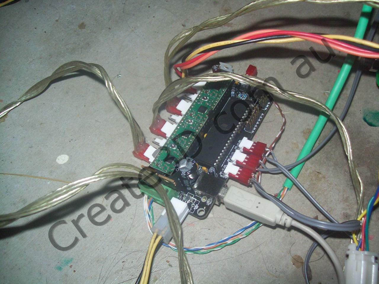
Insert your A4988 carriers, connect motors, endstops, thermistors, heaters and begin printing!